Designed around your part samples
Bowl feeder tooling is confirmed from samples because component shape, centre of gravity, surface finish and required exit position all affect the route.
Product route
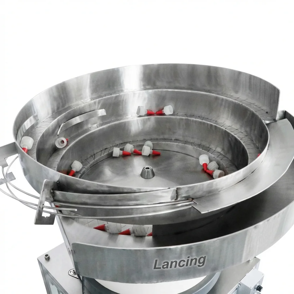
Tooling is the part of a bowl feeder that turns a vibrating bowl into a reliable orientation system. Lancing UK helps specify bowl tracks, reject tooling, chutes, escapements and handover points around real component samples.
Specification advice
Tooling is the part of a bowl feeder that turns a vibrating bowl into a reliable orientation system. Lancing UK helps specify bowl tracks, reject tooling, chutes, escapements and handover points around real component samples.
Important considerations
Bowl feeder tooling is confirmed from samples because component shape, centre of gravity, surface finish and required exit position all affect the route.
Projects often need part rejection, singulation, orientation correction, final chute control, level sensors and integration with the downstream capping machine or assembly station.
A feeder bowl alone does not solve orientation. The correct tooling is what improves feed stability, reduces jams and gives the capper, filler or fixture a consistent presentation.
FAQ
Bowl feeder tooling is the custom track, reject and chute arrangement inside and after the bowl that controls how the part is sorted and presented.
Yes. Sample parts are strongly recommended because bowl feeder tooling depends on real component geometry, weight, material and the required final orientation.
Yes. Bowl feeder tooling is commonly used for screw caps, pumps, triggers, sprayers, crown caps and other production components.
Related routes
Send Lancing UK your samples, photos, dimensions and target output for a practical feeder recommendation.
Engineering specification
These notes add the practical information buyers usually need before Lancing can confirm a feeder route, tooling approach and line interface.
Bowl feeder tooling should be assessed with real samples. Lancing will need the component geometry, material, finish, centre of gravity and the exact orientation needed at the discharge point.
View sample requirementsThe design route considers component geometry, material finish, recirculation path, tooling access and change-part limits. Wrongly presented parts may need to be rejected, corrected or recirculated before they reach the downstream equipment.
View tooling guideThe discharge height, chute handover, sensor positions, start/stop signal and PLC interface should be checked before the quotation is finalised.
Integration checklist| Feeder planning point | What to confirm | Why it matters |
|---|---|---|
| Suitable parts | Caps, closures and components where orientation is created by the track, rails, wipers and reject features | Confirms that this page owns the orientation and feeding problem rather than the complete packaging machine decision. |
| Target rate | Target parts per minute, acceptable surge and whether the feeder must avoid starving or flooding the downstream machine. | The rate is part-specific and should be proven against the actual component and discharge route. |
| Change parts | Which caps, closures or components must run on the same system and how quickly changeover needs to happen. | Some formats can share tooling; others need dedicated bowls, tracks, rails or chutes. |
| Environment | Noise constraints, static risk, product cleanliness, material finish, coating and operator access. | These factors influence bowl lining, covers, sensor selection, guarding and maintenance access. |
These answers are based on the feeder information visible on this site and avoid unsupported speed, price or stock claims.
The useful starting point is sample parts, drawings or dimensions, material, weight, required exit orientation, target feed rate, downstream machine details, discharge height, footprint and any control interface requirements.
Sometimes, but it depends on how close the parts are in size, weight, shape and orientation behaviour. Multi-format use should be checked with real samples and agreed changeover limits.
Geometry, surface finish, weight, nesting behaviour, static, tooling wear, track loading, sensor position, chute handover and the downstream machine demand can all affect consistency.
If the component tangles, marks easily, has no stable orientation features or needs a very different presentation method, a linear feeder, escapement, hopper, magazine or another handling route may be better.
Agree whether the feeder must start and stop from the downstream machine, whether level sensors are required and whether a sensor or PLC interface is needed for jam, full-track or low-part conditions.
The bowl tooling and reject route are designed around the actual part. Samples expose mould variation, coating, static, balance and change-part issues that drawings alone can miss.
Tooling elements
Tooling is the part-specific part of the system. It is used to separate, orient, reject, recirculate and present components so the downstream machine receives the right part in the right position. The same bowl drive can behave very differently when the tooling changes.
| Tooling area | Purpose | Specification questions |
|---|---|---|
| Track geometry | Guides parts through the bowl path while encouraging the required attitude. | What orientation should leave the bowl, and which positions are unacceptable? |
| Selectors and rejects | Remove wrongly presented parts before they reach the final discharge. | Can rejected parts safely recirculate, or do they need a controlled return route? |
| Escapements | Present one component at a time to a pick point, fixture or intermittent machine. | Does the downstream process need single release, buffering or a presence signal? |
| Chutes and transfer tracks | Move oriented parts from the bowl to the machine interface. | What height, angle, length, sensor point and guarding are required? |
| Lining and coatings | Help with noise, wear, friction, marking or static-sensitive behaviour where suitable. | Does the part mark easily, generate static, carry dust or need extra cleaning access? |
Tooling may need to distinguish open side, thread direction, hinge position, tamper band shape or skirt detail before the cap reaches the chute.
Plastic cap orientationIndustrial parts may need more focus on separation, nesting, weight distribution and final presentation to a fixture or pick position.
Component feeding systemsJam points, recirculation behaviour, wear areas and operator access should be reviewed before the layout is finalised.
Troubleshooting guideThe bowl creates movement, but tooling creates the usable orientation. Without the correct tooling, the feeder may move parts without presenting them correctly.
Some settings can be adjusted, but the practical scope depends on the tooling design, part variation and downstream machine interface.
Wear, loose fasteners, changed parts, dirt, incorrect vibration settings, damaged chutes and downstream restrictions can all change tooling behaviour.
Not always. Recirculation depends on the part and the risk of marking, damage, nesting or repeated jams.
Tooling design
Good bowl tooling uses repeatable component features and gives rejected parts a controlled route back into circulation.
Tooling can use the way a component balances on a rail, ledge or track to distinguish one attitude from another. A correctly oriented part may remain supported while an unstable attitude loses support and falls away. The method must tolerate normal variation and avoid relying on an unrealistically precise balance point.
A tolerant reject feature separates accepted and rejected attitudes across the real production range, not just one nominal sample. Clearance, support, guide position, surface condition and vibration level should allow normal good parts to pass while wrong orientations leave the track consistently.
If most parts repeatedly return to the bowl, the system may have an unnecessarily narrow acceptance window, unstable pre-orientation or a reject point that is too sensitive. Excessive recirculation can reduce usable output and increase part contact, so trial observations should record how many passes parts need before acceptance.
Operators and maintenance staff need safe access to likely build-up points, reject features, narrow tracks, sensors and the final discharge. Access should be considered before guarding and covers are fixed so that cleaning or adjustment does not require disturbing unrelated tooling or losing the agreed datum.
Tooling support
Custom tooling is part of the feeder’s value. Keep a record of reject gates, selectors, rails, coatings, liners, chutes and escapements so future support, spares and format changes are based on the actual supplied arrangement.
| Record | Use | Related page |
|---|---|---|
| Accepted part and orientation | Confirms what the tooling was designed to present. | Sample requirements |
| Wear and liner points | Helps diagnose marking, noise or feed changes over time. | Spares planning |
| Inspection or reject features | Shows which features reject, recirculate or release the part. | Inspection integration |